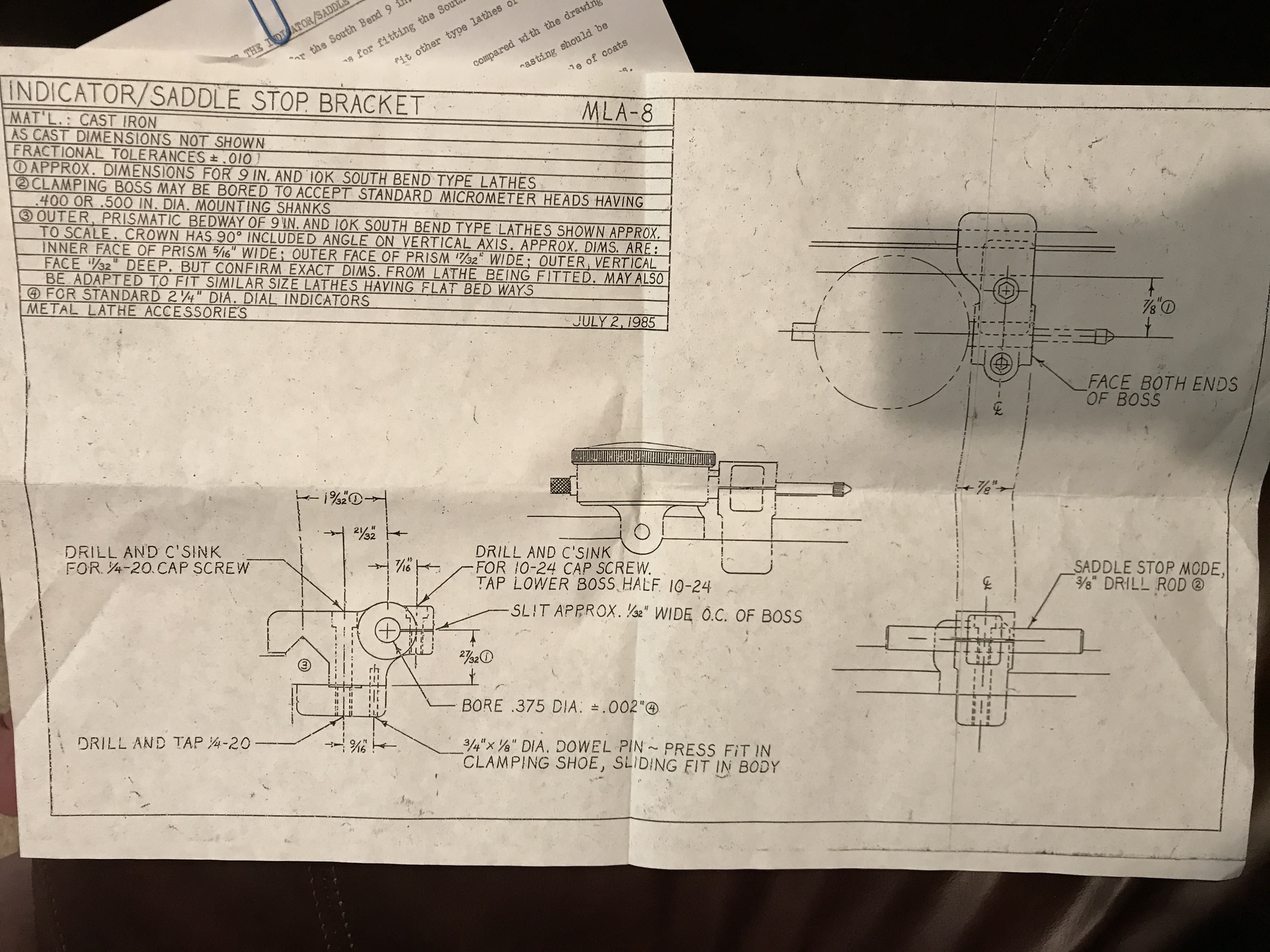
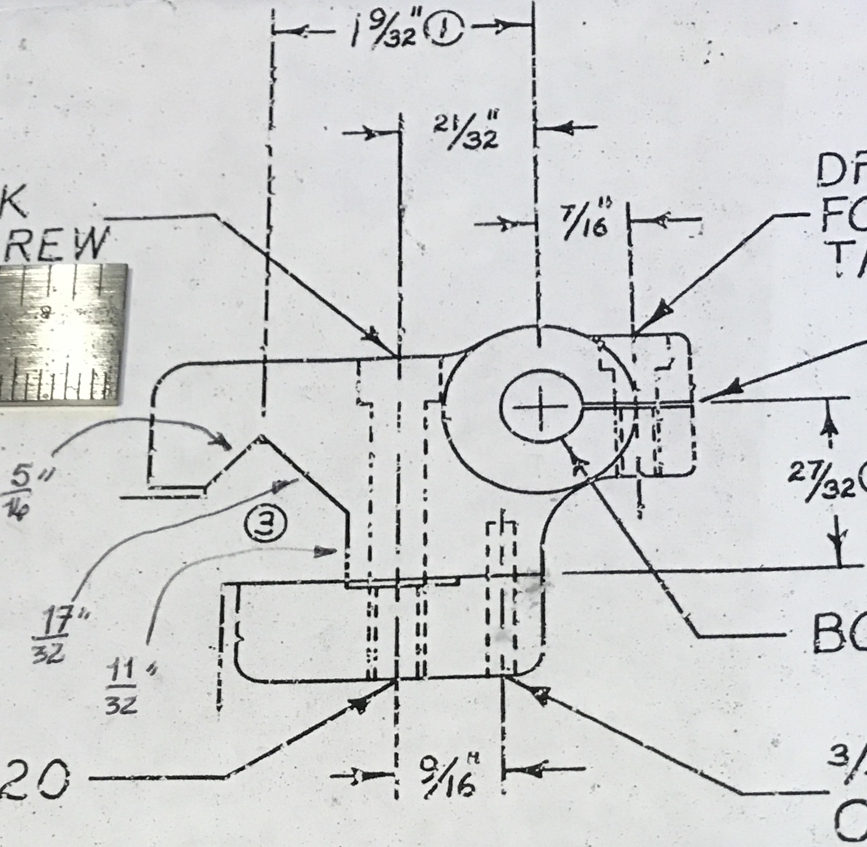
I was getting antsy working for so long on decorating the orrery, so I decided to start another project. This is the MLA-8 Indicator and Saddle Stop Bracket for the South Bend 9" lathe. The main bracket is a casting. It was painted first with a few coats of enamel to match the lathe. The plans are clear, but the instructions are minimal. A picture of the plans (though not so clear) is included below.
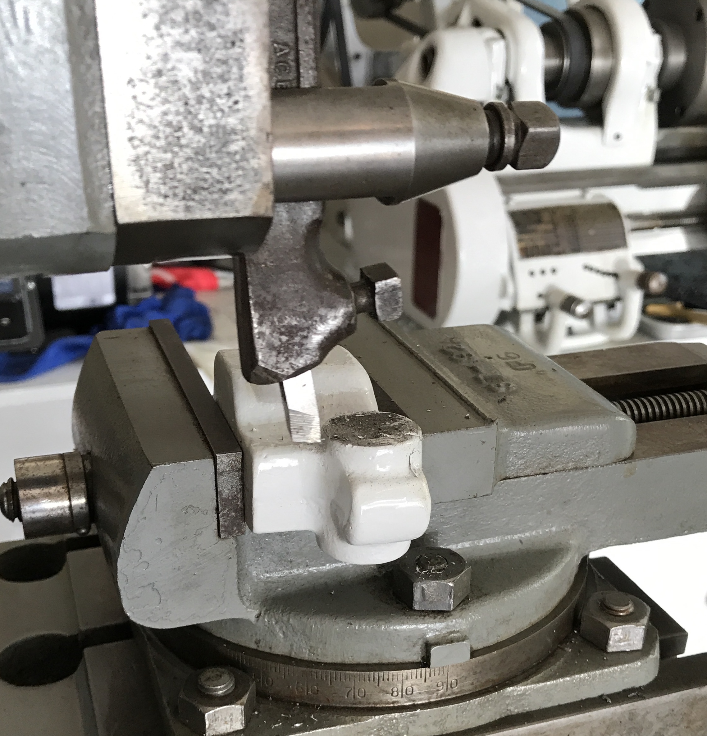
The casting was held in the vise on the shaper and about 1/8" of material was removed on one side of the boss. A picture of the part in the vise is included as is a short movie of the shaper in action. A series of 0.010 X 0.010" cuts was made. A finishing cut of 0.005" depth ended the cutting. The part was flipped over and an attempt was made to level the previously cut face. Again 1/8" of material was removed. The two faces so created were far from parallel.
Used the 2-insert cutter in the mill to align the faces of the boss. When finished they were about 0.020" off and pretty parallel with the sides of the casting. A machinist's jack was used to support the end being cut and cardboard was set between both vise jaws and the part. The dial indicator was used to set the alignment of the casting and paper shims were used to get it close to true.
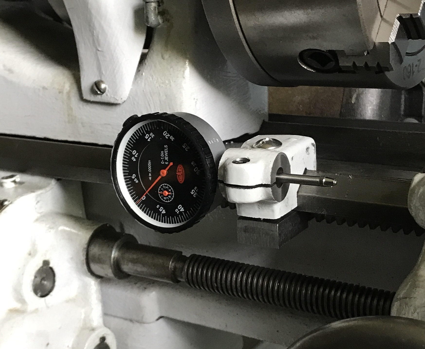
Again the casting was trued up with shims in the vise indicating on the newly cut boss surface. The center was marked and the boss was drilled through with a 1/4" drill using a lot of cutting fluid. The shaft of the indicator to be used is 0.374" in diameter, so this was followed by a 23/64" drill. Unfortunately, the setup was on the mill and the 3/8" reamer was too long to fit between the casting and the drill chuck. An adaptor was made to hold the reamer in the Sherline collet. A 1 5/8" piece of 1/2" aluminum round was faced and the diameter reduced to 0.375" for 5/8". A flat was filed on the reduced end with a three corner file. This end that now fits the Sherline collet was held in the Sherline collet and the opposite end was faced. This end of the holder was reduced just sufficiently to clean up the outside of the part. A hole was center drilled and drilled to 0.277" and then bored to 0.310" to fit the reamer. This same end was cross-drilled completely through on the drill press 3/8" from the end and tapped 6-32. Two set screws were found to hold the reamer in place. The ends and holes were all chamfered. The part with reamer was still just a little too long to fit so the length of the end that fits the collet was extended about 5/16". This worked well and the hole was reamed with the 3/8" reamer.
Finally, returned to the saddle stop after almost a year. First, some measurements were marked on the stop body. A 3/8" transfer punch was inserted in the hole and measurements were measured relative to the point of the punch. The two holes were marked out. The location of the bottom of the vee groove was marked. The distance to the bottom was also marked.
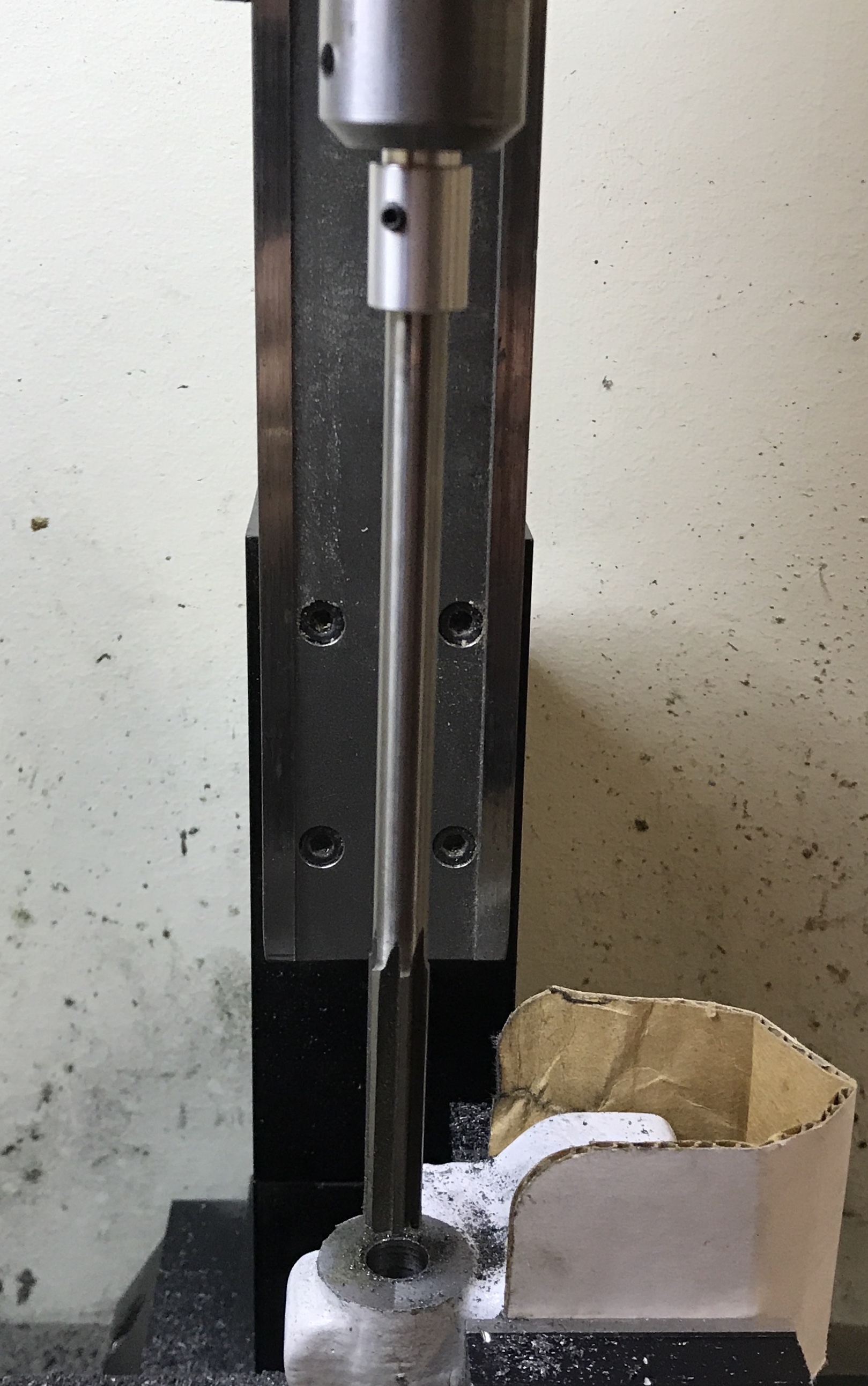
Second, the bottom was cut to the line on the shaper. The shaper would not cut at the beginning. After sharpening the tool it still would not cut. I decided the cast iron was too hard on the outside. I filed most of the surface off. Then the shaper cut fine. Two problems were noted. First, the tool would on occasion catch on a hard spot on the front side of the stop and leave a big groove in the surface. Second, the leading edge of the surface was always a ramp up to the final cutting height. This "ramp" is about 1/16" wide. I am not sure how to remedy either issue. During the many cuts (0.010" X 0.010") the bottom pulley attached to the motor shaft kept coming loose. I filed the flat on the shaft on two occasions. This may have been the key to keeping it tight with the set screw. The upper pulley this pulley is belted to also came loose once as did the collar behind it. In any event I eventually cut through the mark on the side of the stop. I stopped at this point to take a measurement. Setting the stop's machined face on the granite and measuring up to the inserted punch shows an additional 1/16" needs to be removed. A photo of an early stage in the cutting and one of the surface of the stop are shown below.
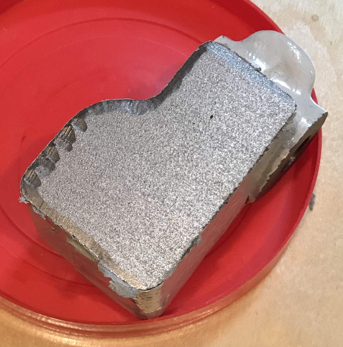
Note the multiple grooves where the cutter caught on some edge hard spot. This last pass was worse than most. Note also the "ramped" edge. I will try again after shortening the length of the exposed tool.
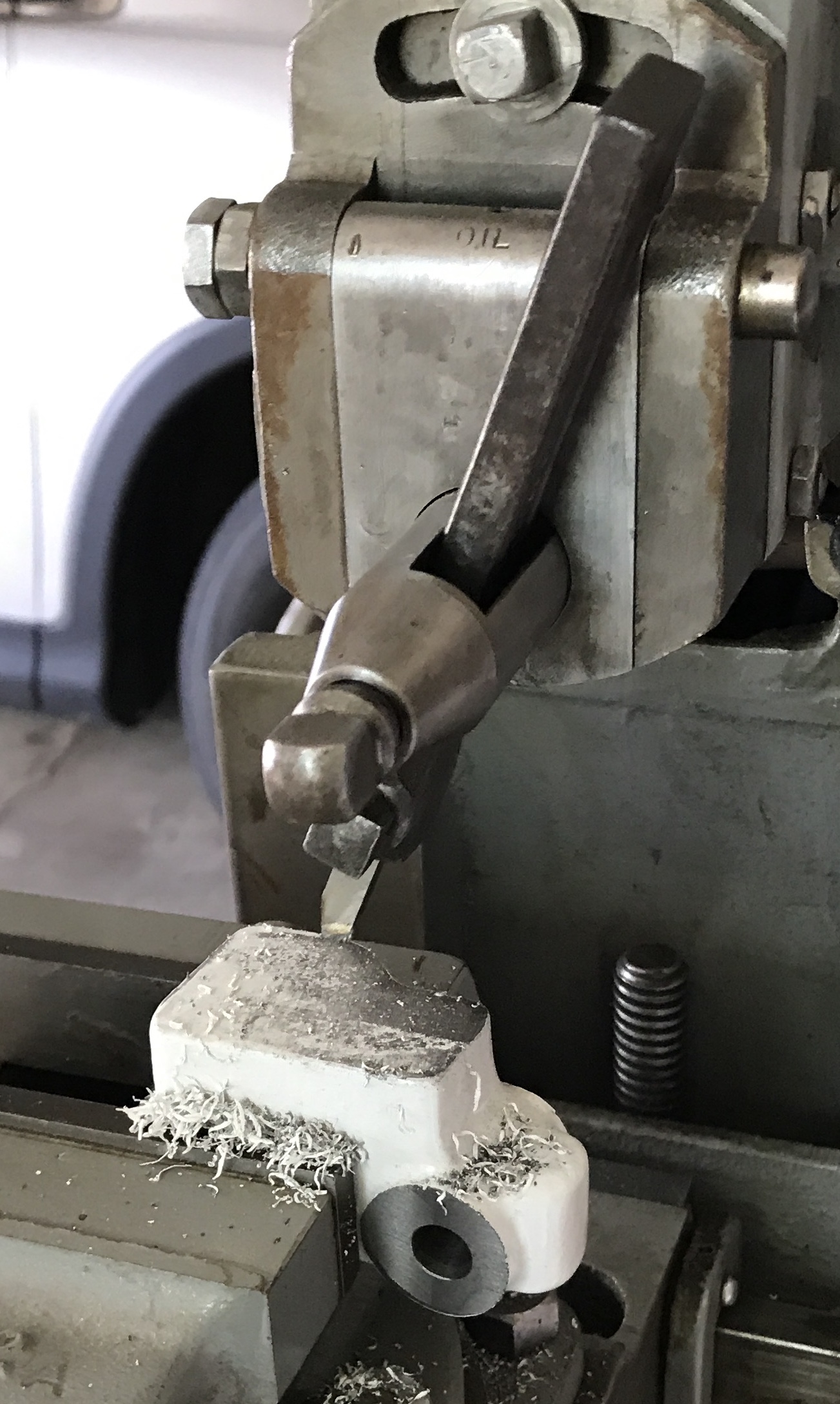
The tool was removed from the tool holder and shortened by about 1/4" on the bench grinder with water cooling. The cutting faces were briefly reground. Upon inserting the tool into the holder only about 3/8" was exposed. The tool holder was also pushed as far into the tool post as possible. Finally, the leading edge of the stop was filed at a 45° angle to remove any potential hard spots. The cutting went extremely well and took about one hour: five minutes per pass. There was no "ramp" left on the leading edge or on the sides. No hard spots were encountered. The picture below shows the result. (Note how little tool is exposed.)
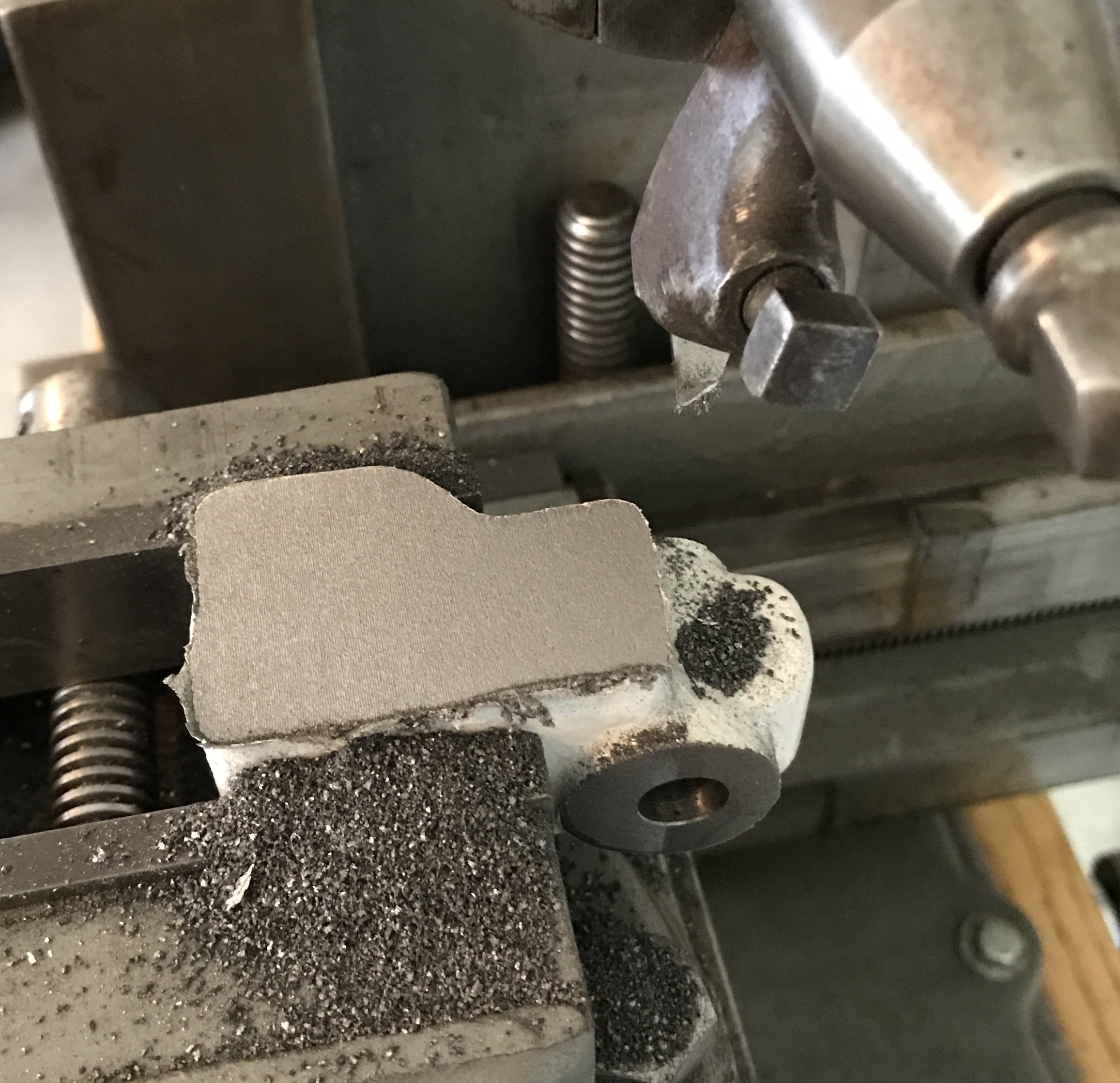
The surface finish is still not very smooth as can be seen in the picture. The shaper has a lot of vibration. It has walked a few inches. There is a rattling noise coming from inside the machine as it cuts. It sounds like it is the eccentric mechanism that is making the noise and may be the source of the vibration. It will need to be taken apart to determine what is loose or worn and what can be replaced or repaired.
The next task is drilling the cross holes in the stop. The hole that clamps a shaft in place is drilled 10-24 through for half of the depth and tapped the other half. A 10-24 tap needs a #25 drill. This will be followed by a 7/32" clearance drill. Finally, a countersink will be drilled 0.190" deep with a 5/16" drill. The above process was followed without any issues and the bottom half of the hole was tapped.
The cross hole for clamping the stop to the ways is simpler. A through hole for a 1/4-20 cap screw was drilled with up to a 9/32" drill. The hole has not been countersunk. The only 1/4-20 screw available has a round head. A slitting saw was used to cut the slot. The saw was aligned with the middle of the hole for the rod (or gauge) by eye. The cut was then taken in 0.010" increments. The cutting went smoothly. A short 10-24 screw was installed in the hole. When a 3/8" rod (end mill) was inserted in the hole, just a slight turn of the screw held it tight.
The next step is to make and fit the shoe. First the block of steel needs to be squared up. This will be done in the shaper. Then it needs to be cut to dimension. A hole for the dowel rod needs to be drilled. When the mating hole in the stop is drilled the two can be put together to mark the clamp screw hole in the shoe. A shallow slot also needs to be cut in the shoe per the plans.
Used the shaper to square the ends of the block of steel for the shoe. Then continued with the shaper to remove about 1/4" of material from one face. Started with 0.010" cuts and then moved to 0.015" depth of cut. The finish was no different. The size did not come out correct so redid the part. Cut off a 1 7/16" length of 1/2" X 1" rectangular steel with a hacksaw. The ends were squared up in the shaper and the length reduced to 1 3/8". The shoe was placed on parallels and the 1" width was reduced to 7/8" in the shaper.
The shoe was aligned with the body of the stop and clamped. A transfer punch was used to mark the location of the hole for the screw. The hole for the pin was laid out 9/16" to the right of this first mark and on center. This mark was punched. The shoe was transfered to parallels in the Sherline mill vise. It was center drilled and drilled through with a #32 (0.116") drill. The hole was reamed with a 1/8" reamer. The spindle was then aligned with the mark for the transfered hole. It was center drilled and drilled through with a #7 drill. The hole was chamfered and tapped 1/4-20.
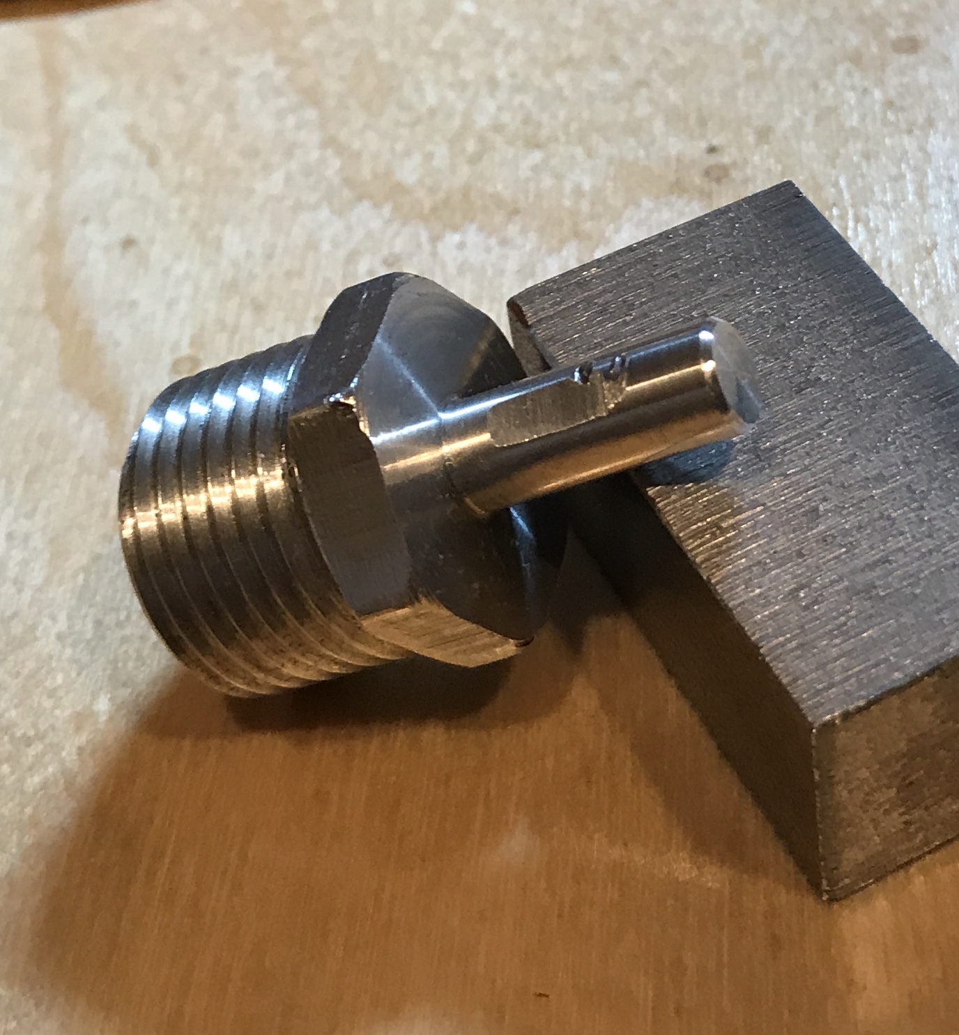
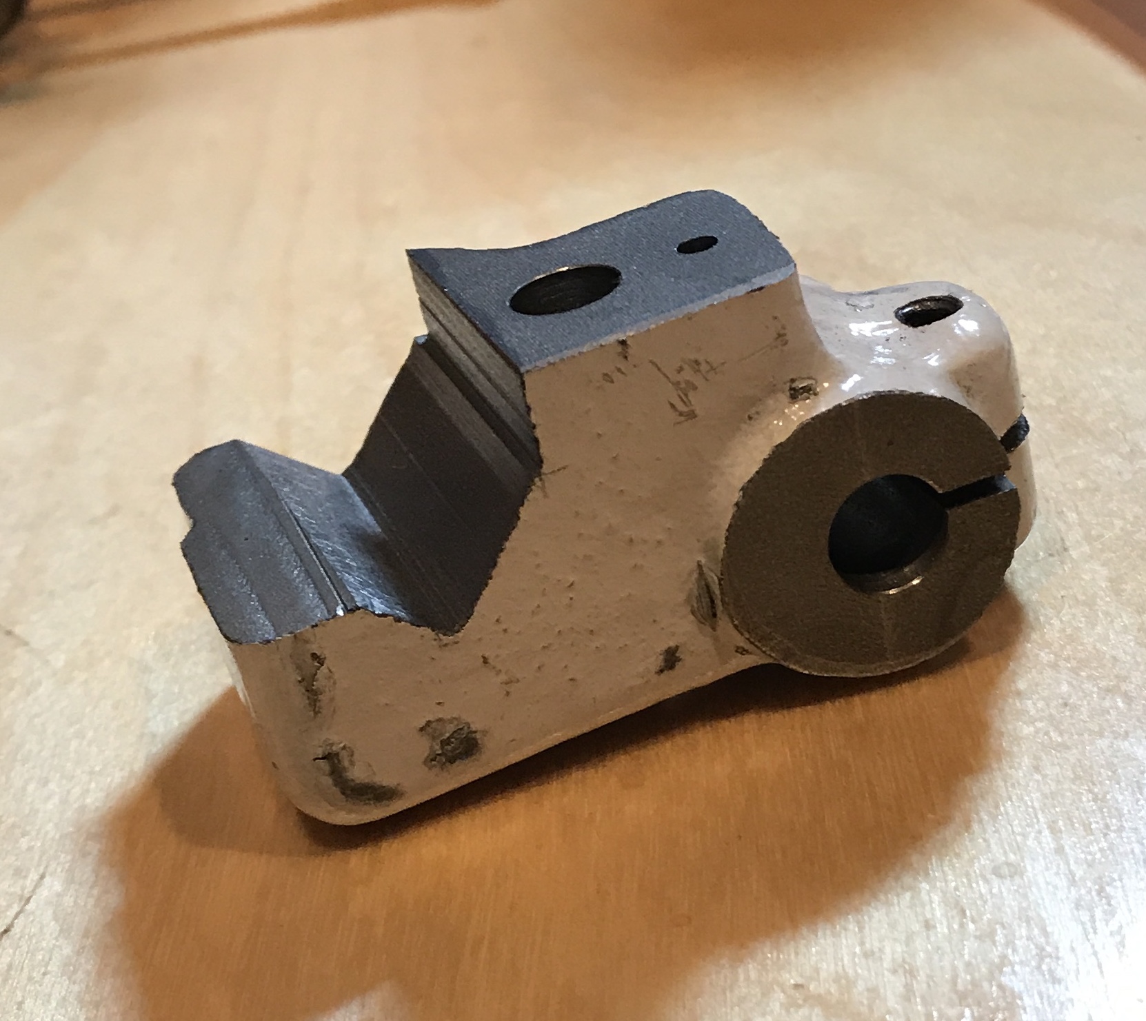
After repeating the drilling procedure in the correct location (though set the dowel hole 7/16" from the center of the tapped hole). This hole was then transferred to the body. The body was drilled #32 and tapped 1/8" to a 3/8" depth. A 3/4" length of drill rod was placed in a collet and one end faced. This end had the diameter slight reduced with a light cut and some sanding until it was a sliding fit in the dowel hole in the body. This pin was then press fit (with a drop of loctite) into the shoe. A picture of the two parts is included below.
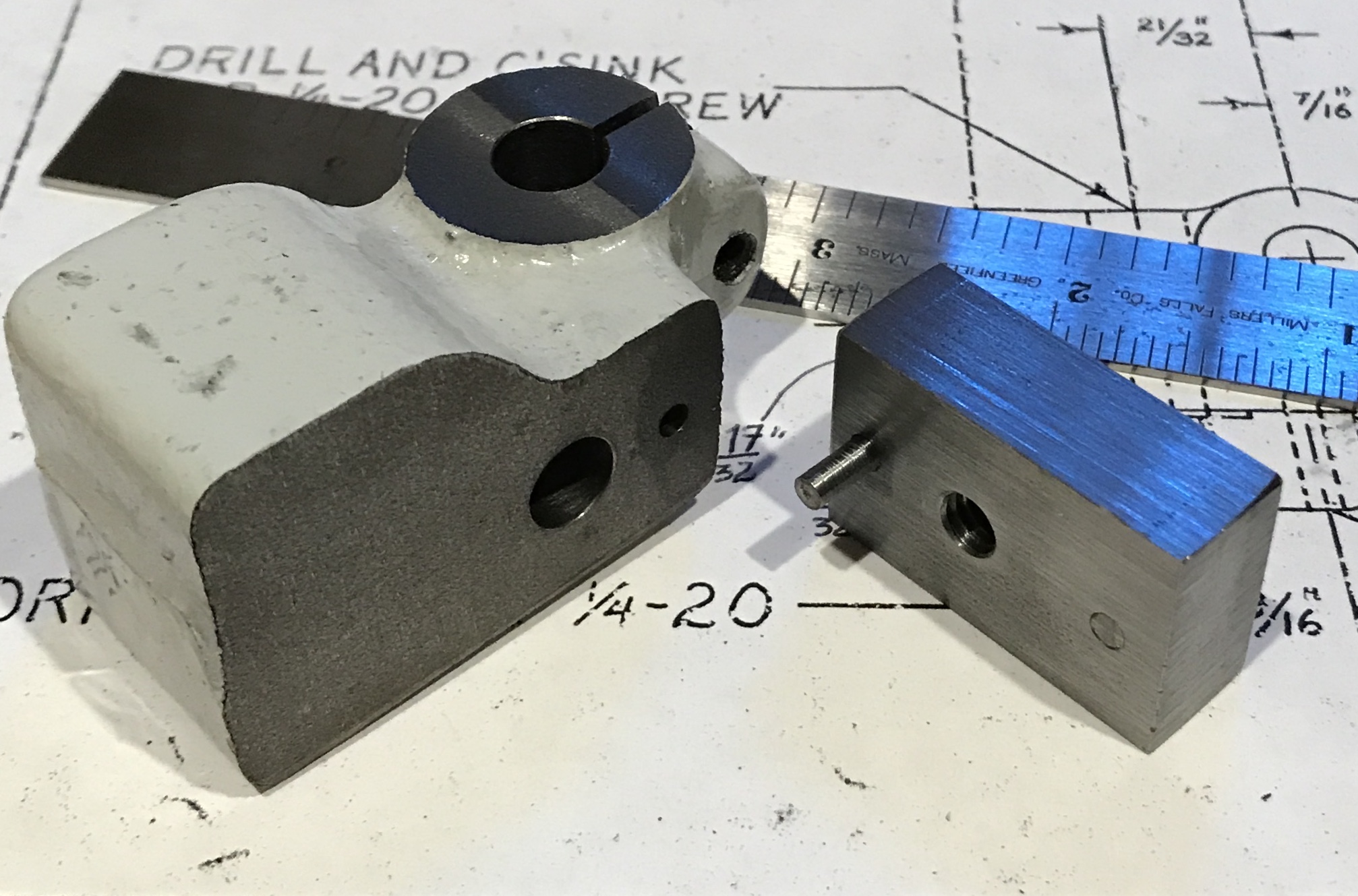
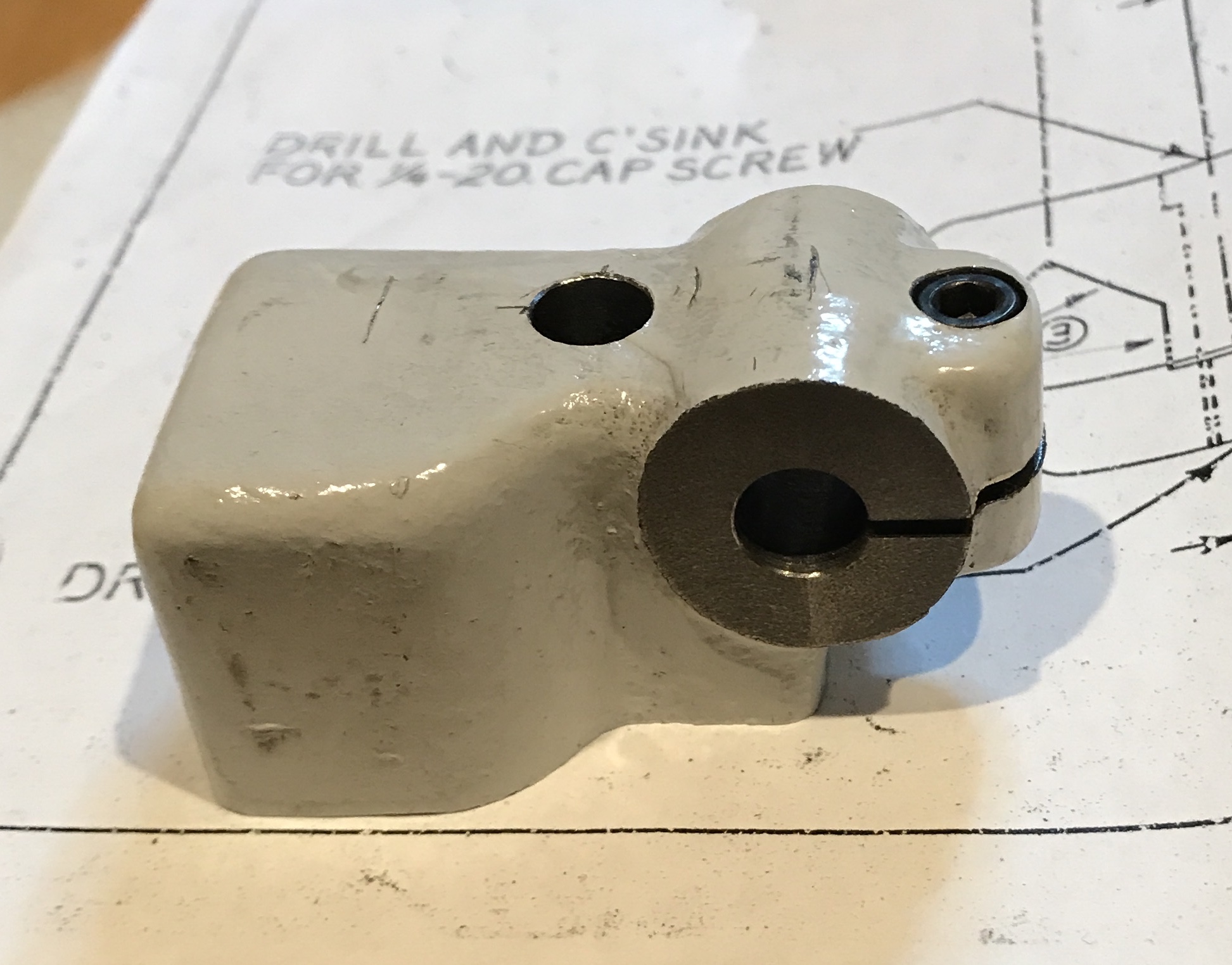
A slot now needs to be cut in the body side of the shoe around the tapped hole. From the plans is appears to be about 1/64" deep. One side of the slot aligns with the wall of the body that presses against the outside of the lathe way. I will postpone slotting until I have cut the lathe way profile in the body. The profile can then be used to accurately mark the edge of this slot. A closeup of the body and shoe detail is shown above.
The profile in the body will be cut on the shaper with a series of three cuts, if I can figure out how to use the shaper for slotting. The first cut will be a square to the main wall. It has an 11/32" arrow pointing to it. The second cut will be along the surface that sits on the inside of the lathe way almost to the right angle where the 17/32" arrow is pointing. Finally, the 45° slot will be made.
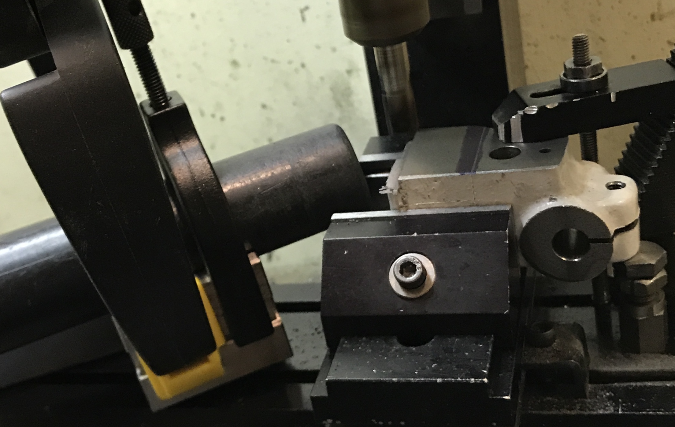
The first cut was made, but with the mill. The internal rattling in the shaper has me worried about using it too much. The stop body was marked for depth, 5/16", and for width of cut. It ended 29/32" from the center of the 3/8" hole. The body was clamped in the vise, supported with a machinist's jack and clamped above the jack with a strap clamp. Machining cast iron produces so much dust, I decided to use a vacuum. After some ineffective attempts the nozzle was clamped in a vee block and the vee block was clamped to the angle plate set at an angle. The setup is shown in the photo below. The cuts were made 0,020" deep and 0.150" wide, except for the last cuts against the wall that was 0.050" X 0.050". A 5/16" end mill was used. The cutting went well and little dust was left on the table. Thank goodness for my hearing protection.
In order to cut the vee groove the clamping assembly needed to be moved to the right side of the table. After numerous issues were dealt with the corner of the end mill was aligned with the bottom corner of the vee groove. The cutter was lowered into the work. It was then that a new problem arose: the end mill can't descend low enough. With the head set at 45° the lowest travel has been reduced so the end mill stops about 1/4" too high. The part was already on parallels and held by about 1/4" in the vise, so it could not be raised. Either the vise needs to be raised, the end mill extended, or the vertical extension to the mill needs to be removed.
Option 2 was selected. I have a second end mill collet for 1/4" end mill shafts. The simplest plan was to make an adapter that would link this collet to the collet holding the 5/16" end mill. A 1 1/4" length of 3/4" aluminum hex was cut off with the hacksaw. This was chucked in the lathe and faced. 5/8" was reduced to 1/4". The end was chamfered. A flat was filed on this reduced portion. This 1/4" shaft was put into the 1/4" end mill holder and attached to the spindle. About 1/2" of the exposed hex was reduced until it was round. Thread relief was cut at 1/2" with the parting tool. The lathe was set up for screw cutting. Threads, 3/4-16, were cut in the part to a depth of 0.040". This was a little deep for a tight fit in the collet. After clean up the adapter was complete. A photo of the finished adapter is shown below.
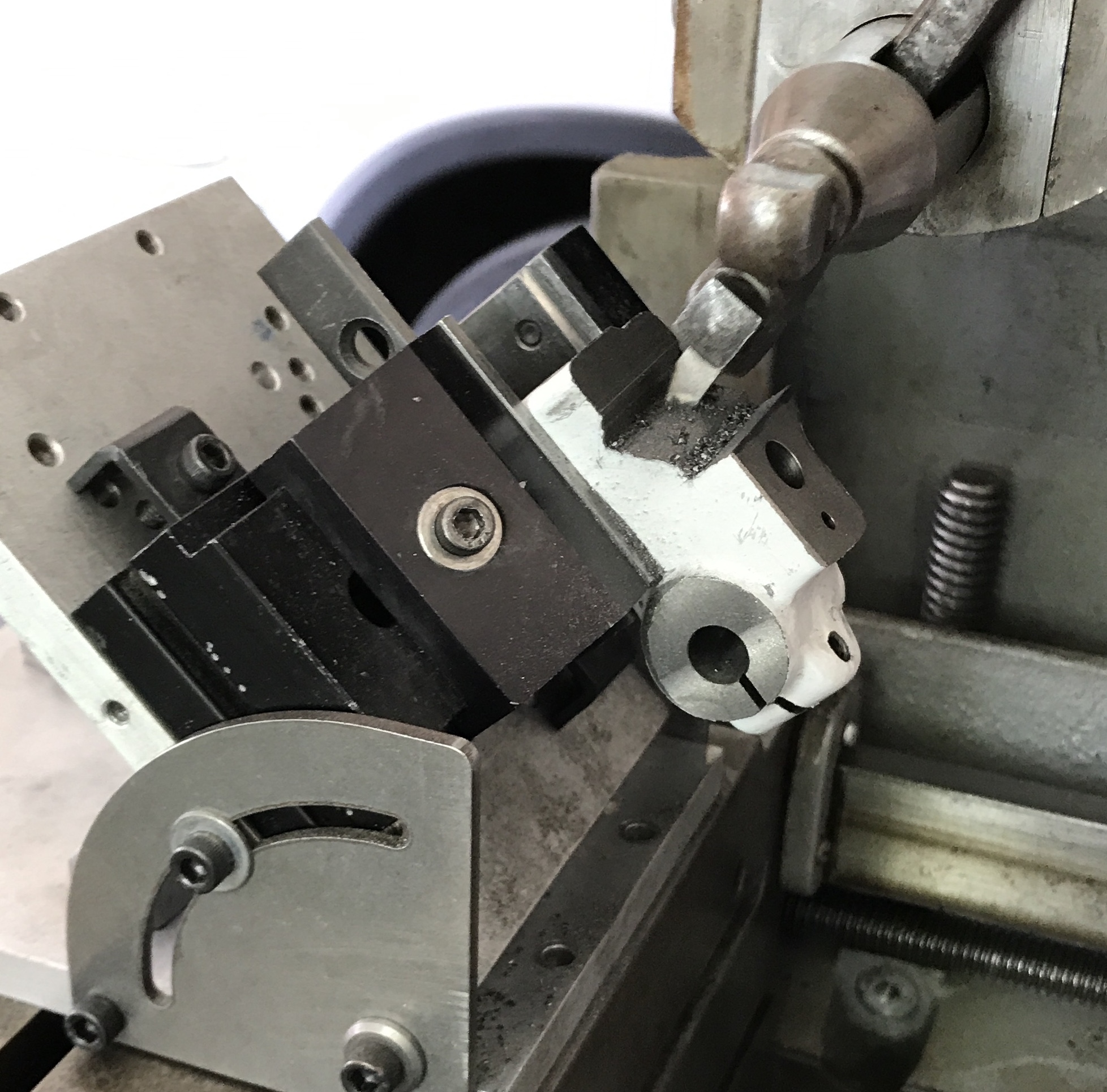
The extension is nice, but milling the part did not work. There was too much chatter. I attempted to set the part on a 45° angle with the angle plate holding the vise, but this also resulted in significant chatter. So I took the vise on the angle plate to the shaper. The angle plate did not fit in the shaper vise. The t-slots in the shaper table were measured. These measurements were marked on the base of the angle plate. 3/8" holes were drilled and chamfered. Perfect fit! The first picture below shows the setup. I was able to get all the way to the bottom of the vee. (The long side in this case.) It was necessary to stop the movement of the shaper as it got close to the left side of the vee. This was then cleaned up with vertical movement. That is the shaper was moved to the vertical surface, moved over 0.010", and down 0.010" with each pass. When removed from the vise it was test fitted to the lathe ways. It did not sit flush. the vertical side (in the second picture below) was too close. So I will return it to the Sherline and do some side milling on it to open the gap.
Thinking it through now that the vee groove and other milling/shaping is complete. A better way to accomplish the same work would be to thoroughly consider all steps in the process and minimize the number of vise transfers. Each transfer comes with error in the orientation. Keeping each cut square on a casting with no perpendicular sides was impossible with the process used here.
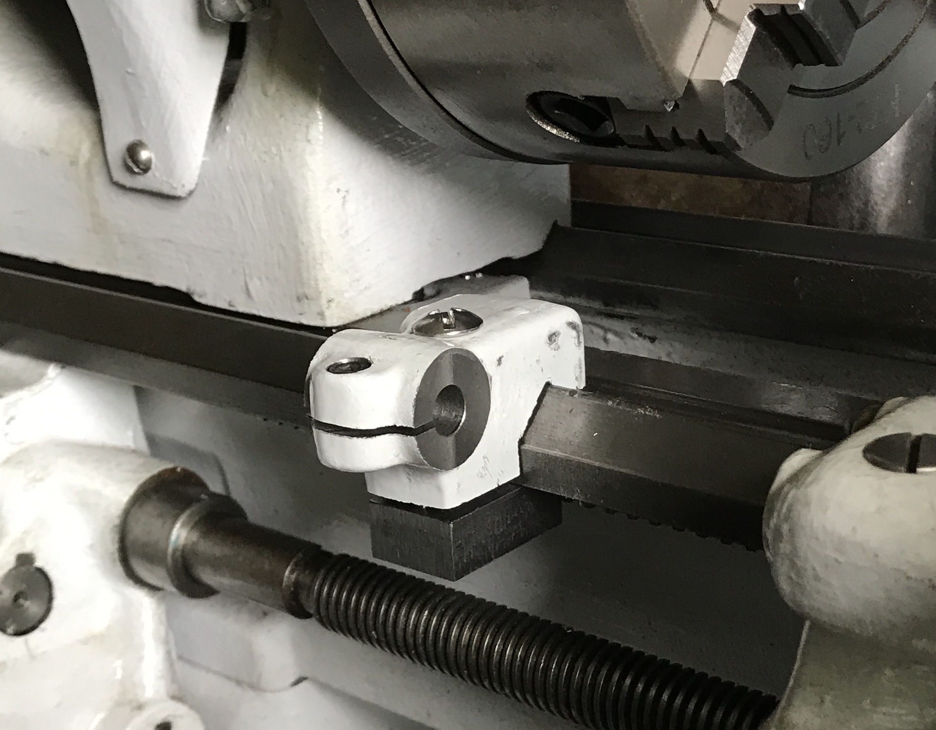
The milling was completed. About 0.030" was removed. It now fits reasonably well on the lathe ways. It works and I am happy! A picture shows the almost completed stop attached to the South Bend lathe ways. I will need to order some 3/8" drill rod to finish it off. Will also cut the slot in the shoe at that time.
The 3/8" drill rod arrived. A 3" length was cut off with a hacksaw. The ends were faced and chamfered. The shoe was finished this morning. A 1/2" wide slot was laid out around the hole on the pin side. A 3/16" end mill was used to cut a slot 0.031" deep in 0.005" increments. The initial slot was widened in 0.015" passes. The burrs were removed and the bottom four edges were chamfered with a file. May decide to paint it someday.